29 February 2012

How to Make a Weatherproof Cable Splice

As anyone involved in the field installation of sensors can confirm, there are times when a diversion from the original plan must be followed. In many instances a sensor’s cable length can be a direct cause or effect of this diversion. In an ideal world, a sensor’s cable will resist aging, repel nature’s most persistent rodents, and always be just long enough to reach any controller. Without further comment on an ideal world, the following will provide details on a tried and true method for making a secure, weatherproof splice, should the need arise.

Supplies needed:
  • Wire Cutters / Wire Strippers 
  • Heat Gun 
  • Solder Sleeve (size dependent on wire diameter being spliced) 
  • Polyolefin Adhesive-Lined Heat Shrink (size dependent on cable or connector being spliced) 
  • Solder Iron (recommended) 
  • Solder (recommended) 

Procedure:


Step 1: Strip outer cable insulation 5/8”, while stripping and tinning the individual wires 1/4". NOTE: tinning the individual lead wire helps to eliminate cold solder joints by cleaning the individual strands and allowing solder to flow more freely.


Step 2: Slide the solder sleeves onto the wires making sure the tinned ends are inside the solder rings.


Step 3: Slide the cable that is to be spliced into the other end of the solder sleeve making sure the tinned ends are inside the solder ring. Verify that the wires are matched to the correct wires from the sensor (e.g., red-red, black-black, and so on). NOTE: depending on the location of the cable splice, you may decide to slide the outer heat shrink onto the cable before soldering the wires together (see Step 5).


Step 4: Heat the solder sleeves using a heat gun until the solder flows. Remove heat and be careful not to pull on cable and individual wires until the solder is set.


Step 5: Cover the junction with a polyolefin adhesive-lined heat shrink. This will seal the splice from the elements. Allow 1” on the outer jacket of cable to ensure a good seal. Use heat gun and notice the heat shrink forming tightly to the cable and splice. The adhesive-lined heat shrink will have a glossy look to it once the glue has flowed. Be careful not to overheat the heat shrink, and allow it to cool completely before moving.


Step 6: There may be a small amount of adhesive coming from the heat shrink ends. This is normal. When done properly, a cable splice can be just as weatherproof as the cable jacket itself. In fact, we use Atum brand heat shrink and have conducted tests showing that it is at least as impermeable to water ingress as the cable’s Santoprene jacket. NOTE: unless otherwise noted, adhesive-line heat shrink has a difficult time adhering to Teflon cable, also known as Polytetrafluoroethylene (PTFE).


Elayne Ballard
Technician


Jacob Bingham
Customer Support and Technical Manager

22 February 2012

Better Know a Distributor – Decagon Devices

The ‘Better Know a Distributor’ series highlights other companies that distribute and resell Apogee products. 


Apogee Instruments has a long history of working closely with our partner company Decagon Devices in Pullman, Washington. We’ve worked together to refine marketing approaches and to develop new products. Our collaboration with Decagon led to the amplified options for our solar radiation sensors and we have also collaborated on workshops at trade shows like ASA and AGU. Last summer Apogee President, Bruce Bugbee, presented a webinar in Decagon’s ongoing web seminar series on measuring solar radiation for plant growth. Decagon resells our quantum sensor (Decagon model QSO-S) for measuring photosynthetically active radiation, our pyranometer (Decagon model PYR) for measuring total solar radiation, and they also use our sensors in products like their comprehensive Microclimate Monitoring System. Like Apogee, Decagon provides their customers with excellent customer support, both online and in person, and have a great team of scientists backing up their products.

Here is an excerpt from Decagon’s website about the history of the company:

Decagon was founded in 1983 by Dr. Gaylon Campbell, a renowned soil scientist at Washington State University. Dr. Campbell was (and is) an old-school physicist. When he wanted to measure something, he built an instrument to measure it. Other people wanted his creations, and eventually he couldn't keep up with the demand. Decagon was formed to build and sell his instruments. 

Decagon has accomplished much in the 29 years since their inception. Their projects have included a thermal and electrical conductivity probe for NASA’s Phoenix Scout Lander mission to Mars. In 2008, they were listed as one of the Top Small Workplaces in The Wall Street Journal.

At Apogee, we appreciate our collaborative relationship and we look forward to our continued work together.


Whitney Mortensen
Marketing & Graphic Design

15 February 2012

Minimizing Problems with Wasps on Weather Stations

Weather stations can suffer damage or the data can be altered due to pests. Pest issues include anything from Elk rubbing the velvet off their antlers against a station, cattle bumping and damaging a station while grazing, vandalism, bird droppings on light sensors, ice buildup, and wasp nests. Each of these issues can reduce data quality and each has many possible solutions.

Wasps can be a problem for many reasons. In addition to an unpleasant human interaction, wasps like to build nests in confined spaces such as in gill-type temperature shields. These nests block airflow and cause elevated temperature readings. Several steps can reduce wasp nests. First, we have found that plugging all open tubes reduces nests in the end of the cross arms We have found that the short vinyl caps from either http://stockcap.com or http://www.caplugs.com work well to fit snugly over ends of cross arms. If the caps are a bright color, this has the added benefit of high visibility to prevent head bumps. Another effective method to plug tube openings is to put closed-cell foam inside the hollow cavities of cross arms.

Once possible nest locations are reduced, it helps to use spray repellent. Some sprays kill wasps and the residue will linger and prevent wasps from returning. Gill radiation shields can even be sprayed with repellent. While this residue can be washed off with moisture, it still helps.

We have used traps to reduce wasp populations around a station. Traps use an attractant to lure in and trap wasps. This is an effective longer-term solution instead of – or in addition to – spray repellents.

Passive, gill-type temperature shields provide a cavity in which wasps like to build nests. We have found that MetSpec temperature shields have reduced numbers of wasp nests, apparently because the gaps that wasps would use to enter the shield are smaller, making it more difficult, for them to enter. Wasps do not like to build nests in areas that are windy. In our experience, wasps never build nests in aspirated temperature shields.

Getting good data goes far beyond sensor and product selection. Ongoing maintenance, such as checking a gill shield for a wasp nest, is critical to gathering good data. We consistently remind our customers that ensuring sensors are mounted correctly, leveled when needed and cleaned periodically go a long ways to getting better measurements.


Seth Humphries
Product Development Scientist

08 February 2012

Apogee Oxygen Sensors

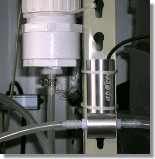
Figure 1: Diffusion Head in use
We sell two types of oxygen sensors: soil and fast response. The soil sensor is designed for direct burial and includes a diffusion head, which has a screen that allows the sensor to measure a larger soil volume. The fast response sensor is most often combined with the flow-through head for laboratory applications. The table below compares the two sensor types.

Soil
SO-110/120
Fast Response
SO-210/220
Output ≈50 mV ≈12 mV
Output Decrease < 0.2% / year < 4% / year
Life Expectancy 10 years 5 years
Response Time 60 s 12 s
Generic Offset 2.5 mV 0.25 mV


Calibration and Correction

Two values are necessary for calibration: offset and multiplier. The offset is the measured voltage when the sensor is in pure Nitrogen gas. It can also be approximated using the table above. The multiplier uses ambient air in a well ventilated area as the standard, which is known to be 20.95% oxygen. The equation below shows how the multiplier is obtained for a soil sensor using the generic numbers.

20.95% / (50 mV – 2.5 mV) = 0.441% Oxygen per mV 

Percent Oxygen is then calculated by the following equation.

(mV Measured – mV Offset) * Multiplier = % Oxygen 

Or if we measure 100 mV then the percent oxygen is:

(100 mV – 2.5 mV) * 0.441% Oxygen = 43% 

An example of these calculations is also in the manual for the sensor.

This multiplier is valid for the current elevation, pressure, temperature, and humidity. We have developed a paper to help you compensate for changes in these parameters: "Understanding Oxygen in Air" (PDF). The effect of temperature follows the Ideal Gas Law (PV=nRT).

Our oxygen sensors include a temperature sensor in the body to make accurate measurements of the internal, sensor body temperature. The temperature sensor is either a thermocouple or a thermistor. These sensors can be easily read with a Campbell Scientific datalogger. For information about reading the output of the thermistor without a datalogger, please see this blog by Adam Del Toro: How to take IRR Temperature Measurements without a Datalogger. 

Heater

We are often asked why we include a heater in this sensor. A small heater is necessary to keep the sensor about 1 C above ambient temperature, which keeps moisture from condensing on the porous gas-diffusion membrane of the sensor. If moisture condenses on this membrane the sensor output will immediately flatline and begin to slowly decrease. The heater draws only 74 mW when powered by 12 V. This is a very small power draw and we recommend that everyone power the heater in soil environments. If moisture condenses on the sensor it must be placed in a dry location until the readings resume. The heater is not powerful enough to dry the sensor once moisture has condensed on the membrane.

Position

The sensor should be mounted in a vertical position with the head down. This allows the electrolyte inside to always be in contact with the electrodes. With these considerations you should be ready to make accurate measurements.


Skif Smith
Electrical Engineer

01 February 2012

Weather Mapping

Last Wednesday the USDA released a new Plant Hardiness Zone Map. There were several significant changes in this update from the previous map that was released in 1990. The change that has garnered the most media attention is a general shift in many areas of about five degrees Fahrenheit warmer than the previous map (for this blog post all temperatures will be listed as Fahrenheit). The map divides the geography into 10 degree bands labeled with a number, which is then subdivided into A and B bands of 5 degrees. The current map as well as the previous version is available for download at their website. Does this shift indicate a climate change? The USDA points out on their website that climate change is based on temperatures readings from a period of 50 to 100 years. This map is based on 30 years of data (1976 – 2005) and would thus not be a reliable indicator of climate change. Additionally, the data displayed on this map is the average of the lowest winter temperatures for a given area or essentially how cold you can expect it to get each winter in a given zone.

Another change with this new map is the finer scale. Through the Geographic Information System technology used by the USDA ARS and Oregon State University’s PRISM Climate Group, an amazing level of detail and accuracy has been obtained. This is due in part to the implementation of a sophisticated algorithm used to interpolate data between reporting stations. Another significant component in the finer scale is the increase in observation stations. While the number of stations is not available, the USDA website does state “the new map used temperature data from many more stations than did the 1990 map.” In the past seven years I have seen weather stations become more affordable while the quality improves. This has made it possible for more people to measure the environment around them.

As part of our work developing sensors for measuring climate change, sustainable food production, and renewable energy Apogee has had great opportunities to work with research and educational institutions to make weather and climate data available to the general public. Utah State University erected a solar powered environmental observatory in 2011 (http://weather.usu.edu). We have also worked with the North Dakota Agricultural Weather Network (NDAWN), Oklahoma Mesonet, and the AgWeatherNet from Washington State University as well as others. Recently we were notified of a paper published in Plant Methods that used our infrared sensors in researching global warming scenarios in rice paddies. The impact we have on our environment will continue to be studied and as we measure our world, Apogee Instruments will continue to design and manufacture sensors to help make better measurements.


Devin Overly
General Manager